


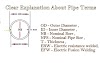
● Globe valve
● Diaphragm valve
● Ball valve
● Taper plug valve
● Butterfly valve
● Check (non-return) valve
● Relief valve.
1. Gate valve :-
Because of the disc and seat design, the gate valve is for on & off use, and not for throttling applications. If gate valves are used for throttling applications, they may damage the disc and seat through erosion or vibration.They have the advantage that, when fully opened, the resistance to flow is low with a minimum of pressure drop, as the fluid flow moves in a straight line.

2.Globe valve :-
The term ‘globe valve’ is applied loosely to a valve whose body is globeshaped or has globelike features. Globe valves are generally suitable for throttling applications, with the design of the valve determining how closely flow can be regulated. Globe Valves are used in the systems where flow control is required and leak tightness is also necessary. 
Types of globe valves include:
Angle globe valve:-
Angle globe valve:-
An angle globe valve changes direction through 90°.

Needle valve :-
A needle valve is a small valve used for precise flow control.

Because of its smooth flow pattern, a wye valve is preferable for use with erosive fluids.

Diaphragm Valve:-
The diaphragm valve is generally used where particles or fibres are carried, eg slurries. The diaphragm is capable of sealing against these particles and it gives full, unrestricted flow in the fully open position. The disc is usually a rubber diaphragm.

Ball Valve :-
A spherical ball is used to block the bore of this valve and cut off the flow. The ball,
which has a hole through it, is rotated 90° by a lever and flow is permitted when the
hole through the ball lies along the pipe axis.

Similar to a ball valve, a tapered (conically shaped) plug is used to seal the bore of the valve. A hole through the plug is used to permit flow when this hole is lined up with the axis of the pipe.
Ball and plug valves are quick and easy to operate and require only a 90° turn of the lever to open or close the valve. When these valves are closed, they pocket fluid in the ball or plug, which may create problems when used with corrosive fluids.

Butterfly Valve :-
A butterfly valve has a circular disc, which is approximately the size of the pipe bore in
diameter. This disc rotates around its centre, so that when closed, the disc completely
covers and seals the bore of the pipe.
When fully open, the disc thickness lies along the centre of the pipe.
The contents of
the pipe then pass down and past both sides of the disc.
The butterfly valve has the advantage of 90° on–off operation and does not pocket
fluids like the ball and plug valve.

Check (non-return) Valve :-
Check valves permit flow in one direction only. The valve closes if flow is reversed.

Relief Valve:-
Relief valves are used to prevent build-up of excessive pressure of gas or liquid in lines or vessels. They usually operate against a pre-set spring loading. Relief valves for gas are designed to permit a large flow; a small flow which will rapidly decrease pressure is usually all that is required for liquids.

Valves may be attached to lines or vessels by the following methods.
- Screwed Attachments :- Generally used on small diameter, low pressure lines.
- Flanged Joints :- The body of the valve is flanged to make it compatible with flanges of the same pressure rating. It offers the advantages of easy installation and removal, and is suitable for medium/high pressure applications.
- Butt Weld Attachments :- The valve ends are supplied with standard weld preparation. Although difficult to fit and remove, this is the preferred method for extreme service applications. Weld procedures should be designed so as to minimise distortion of the valve body.
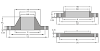
These have no flanges of their own and are sandwiched between the flanges on the pipe ends. They are located and held in position by the bolts which pass between the pipe flanges. Because the pipe flanges are held a distance apart equal to the thickness of the wafer valve, longer bolts than usual will be required.
The valve has flat faces which contact the flanges. Gaskets or O-rings are used to seal against leaks. The outer diameter of the body is made to suit the pitch circle diameter (PCD) of the bolts of the flange. The bolts go around the valve body rather than passing through it.

These guidelines should be followed when valves are being installed :-
- The direction of flow through the valve must be correct. Where this is important, flow direction will be indicated on the valve body (usually by an arrow).
- Valves should be placed in horizontal rather than vertical runs to facilitate the draining of the line when the valves are closed.
- Heavy valves should be suitably supported. A minimum of 300 mm between flange and support should be allowed to facilitate installation and removal.
- For aesthetic reasons, it is important to keep the centre-lines of valves at the same height and in line on the plan view.
- There should be no safety hazards for the operator to contend with when accessing valves.
- Lines carrying hazardous materials should have valves placed in such a way that the operator does not have to reach up to open or close them.
- Valve stems should not point downward at any angle below the horizontal. This prevents sediment from collecting in the gland packing which may damage the stem.
- Valve stems should not be pointed into walkways, etc.


0 Comments